TEACHING KIT CONTENTS:
- CD Drive (Compact Disc Drive)
- DVD Drive (Digital Video Disc Drive)
- CD Media
- DVD Media
- Screwdrivers and wrenches for disassembly and reassembly
TEACHING KIT DIRECTIONS:
| STEP | IMAGES | DESCRIPTION |
| 1 |  |
Required for CD procedures To open and disassemble a CD drive: (1) the CD drive; (2) an Allen wrench; (3) a Phillips screwdriver; (4) a flat-tipped screwdriver; (5) a star-tipped screwdriver; and (6) screw storage. |
| 2 | |
Required for DVD procedures To open and disassemble a DVD drive: (1) the DVD drive; (2) an Allen wrench; (3) a Phillips screwdriver; (4) a flat-tipped screwdriver; (5) a star-tipped screwdriver; and (6) screw storage. |
| 3 |  |
Remove the shell |
| 4 | 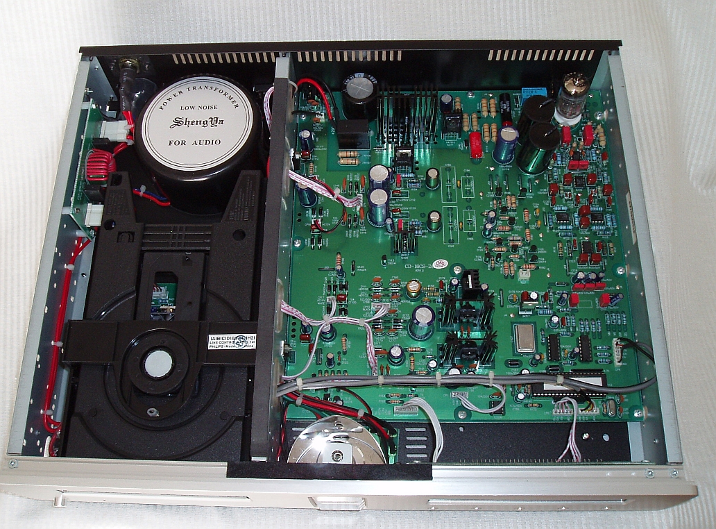 |
Remove the electronics Place the unit upside-down on a soft surface. Remove 4 Phillips head screws securing bottom cover. Set bottom cover aside. |
| 5 | |
Remove the Front Bezel |
| 6 |
 |
Remove the Printed Wiring Board Remove 2 Phillips screws securing Printed Wiring Board (PWB). Gently lift the PWB and disconnect connector to latch solenoid assembly in front of unit. |
| 7 | 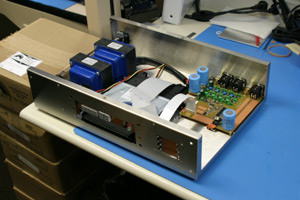 |
Remove the flexible cable |
| 8 | |
Remove the tray assembly Remove the tray assembly Lift the latch solenoid assembly up, remove and set aside. Using a paper clip or similar shaped pin, iers or tweezers, disconnect and set aside the two tray retraction springs. Note their position and orientation. |
| 9 | |
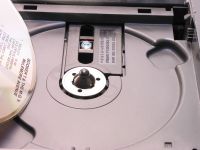
Remove the opto/mechanical assembly Remove the two plastic guides - one on each side. There are little tabs that you will need to depress and then lift each guide straight up. The entire deck can now be slid forward and lifted off. The opto/mechanical assembly can then be removed from the tray. The tray can also be set aside. |
| 10 |
 |
Notes If you prop up the PWB and reconnect the flexible cable - note the orientation marks you made previously - you can then run the drive with full visibility of the mechanism and optics. With a CD in place, there is no danger to you from the laser beam. Just make sure the PWB cannot short to anything and that the whole affair cannot tip over. Reassemble in reverse order. Be especially careful reinstalling the flexible cable. Make sure no wires are being pinched and that nothing is obstructing free movement of the optical pickup. All screws should be tightly secured, resist unscrewing, and could be removed in ether order. |